Why I will be returning a couple of Tiptop Audio ART modules…

I have purchased all of Tiptop Audio’s Buchla 200 Series eurorack modules as they have been released. Initially I was buying 2 of each and then when the spectral module came out, I began buying only one of each. At some point, I bought a couple of the Arturia RackBrute 6U cases and that has been their home. Recently, I had to start rotating out some of the modules because the case is full now. This introduced some opportunity for filling some small holes with other modules (not Buchla related). Some interesting sounds occurred with this change. One of the last Buchla modules that Tiptop released was the 259t – Programmable Complex Waveform Generator. This module has ART functionality incorporated. I began to get curious about what the purpose of this ART input is and that’s where this story begins.

Searching for Answers

When initially searching for more info about ART, it’s easy to get pulled into the Tiptop Audio website and read a lot of vague text about it and how great it is. I suppose I was approaching the tech from an odd angle since my interest was piqued by the Buchla oscillator having dedicated inputs for it. I understood that ART was a polyphonic “standard” that Tiptop invented and I also knew that they have individual VCOs that support ART. I thought that I would need the Octopus or Quantizer module for this Buchla Oscillator, so I ordered both of them. My thought process was that I could output MIDI from my DAW or plug in a hardware controller to the Octopus and output the ART to the Buchla 259t. The manual for the 259t even shows tuning the module with the Octopus and also shows using the Quantizer between the Buchla sequencers and the 259t.

What Have I Done?

This does indeed work and then that’s about all you can do unfortunately. Now, you could say, “well you should have done more research before buying,” or “what did you expect?” I promise you though, that until these ART modules were in front of me, I had these thoughts about how great they might be. Then, I started to use them and immediately felt limited in every way. In my research to write this post, I realized that there is actually text on Tiptop’s website stating that “Octopus is not a 1V/Oct midi to CV and should not be confused as one.” This becomes all too clear when you start to use it with a single 259t oscillator.

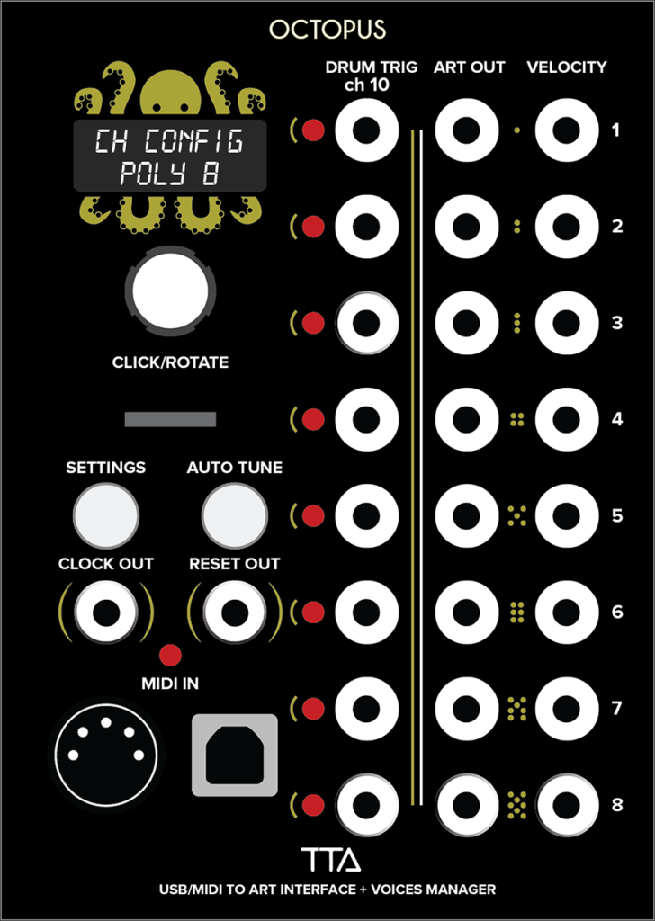
The Octopus module can output 8 ART channels of notes, gates, and velocities, along with 8 drum triggers. These are converted from MIDI. Sounds like a lot, right? It is if you have 8 ART VCOs, 8 VCFs, and 8 VCAs ready to go. Where I really felt my stomach turn was when I had patched up the 259t to two of the 8 ART outputs on the Octopus and I realized that “this is all I can do right now”. I have all these other oscillators, function generators, etc. right here in front of me and these “ART” Octopus outputs will not connect to any of it. If only they could output 1V/Oct as well as ART, this wouldn’t feel so gross.

Help, I Feel Sick
I started to feel pretty disheartened. It is the worst buyer’s remorse I have felt in a very long time. I still felt that all is not lost. Maybe I was missing something. I started looking for an answer and remembered these “polytip” cables that look like USB-C connectors. “What are those things?” I thought. Well, apparently, the products that use those are unreleased as of now. Vortex 6, Octostages Poly Envelope, Octopass Poly Filter, Octogain, and a few other utilities are all planned for release any time now. Currently, if you look at any retailer, there is no price and no preorder. It seems there is a release imminent, but it may be too little too late. I began to discover many others with this sentiment as I did more searching about the subject.

There’s Still Hope

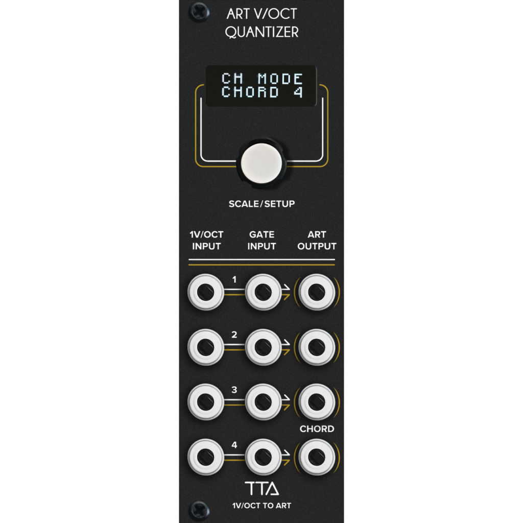
So, Octopus was getting me down. I still had this Quantizer staring at me and I wanted to give it a fair chance. I connected it according to the Tiptop manual example, with my Buchla sequencer to the input and the ART outputs to the 259t oscillator. It works; and I have these 3 additional ART outputs that I have absolutely no use for. That is the problem with this. To utilize the ART system, you will need to spend thousands of dollars up front and then you will have an ART system that only works within itself. The Vortex 6 looks like it may be cool – a PPG inspired wavetable voice. Why not just combine all of this into a desktop synth though, since it appears to be a Tiptop closed system anyways? If you search hard enough, there are rumors of Nerdseq making something to work with ART and another Tiptop poly oscillator with like 16 oscillators in it. How much will that cost? (insert sarcastic eye roll here)

Footswitch and Expression Pedal Circuit Analysis

Recently, I bought the Qu-Bit Stardust, which is a “cosmic” tape looper. It’s actually a really cool looper and I have not used loopers very much. My reason for adding this to my collection is to have a way to layer recordings from non eurorack synthesizers (traditional synths). Immediately, I found a need for a way to punch in and out of recording easily so that I could play along with the loop, but then punch in to record a new part without breaking my “flow”. A footswitch seemed to be the obvious answer, but the implementation in my eurorack system was not so obvious. I had never really considered how a footswitch (or expression pedal) works, so my first course of action was to figure that out.

The Setup

For this example, I am using a Boss FS-6 Dual Footswitch and a Moog EP-3 Expression Pedal. The Boss FS-6 contains a 9V battery and there are switches on the back to allow each of the footswitches to reverse polarity and work in either “Latch” mode or “Momentary” mode. The Moog EP-3 also has a switch on the bottom to switch between “Standard” or “Other”. In addition the EP-3 also has a trimmer knob on the side that “scales the output” according to the Moog writeup about it. I will get into what these do shortly.

What are we even talking about?

First off, a footswitch is just a switch. By engaging / stepping on the switch, you are just closing (or opening) a circuit. This is the first important concept to grasp. The second thing to note is that the footswitch may be opening or closing the circuit. The FS-6 has a polarity switch that allows you to set it either way. The last thing is that the FS-6 can be latched or momentary. For this example, we are going to have the polarity set to normally closed and the latching on. This way, when the footswitch is “off”, the circuit is actually completed through the footswitch. When the footswitch is “on”, the circuit is broken within the footswitch and it remains broken until the footswitch is clicked again.

So, let’s say for an example that we want to send a gate signal to that Stardust looper that I mentioned earlier. We would have to route a constant voltage through our footswitch and when we step on the footswitch, it passes that voltage to the looper. If this voltage remains high, the looper records. Stepping on the footswitch again would open the circuit and the looper stops recording. Let’s get into how this actually works.

The Dual Footswitch Circuit

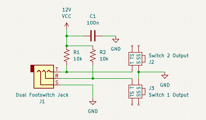
A dual footswitch connects to a device with a typical 1/4″ TRS cable. The tip and ring are connected to switch 1 and switch 2 of the dual footswitch and the sleeve is a common return for both. So on the receiving module in the eurorack system, we have a 1/4″ TRS jack. The positive 12V connects to the tip and the ring of this jack through 2 10k resistors. When I started to research this simple circuit, I immediately found that Doepfer solved this for us a long time ago with the A-177-2 module. It’s such a simple module, that I was able to reverse engineer it from photos alone.

Imagine the dual footswitch plugged into that circuit with the first switch connected to the ring and sleeve of the TRS cable. When the switch is “off” (closed), 12V flows through a 10k resistor and gets shorted to ground through the switch. You press the switch and it latches “on”, which opens the switch and now that 12V does not short to ground any longer, instead it becomes present on the Switch 1 Output jack, giving us approximately a 10V gate output. The same thing happens for Switch 2.

Express Yourself

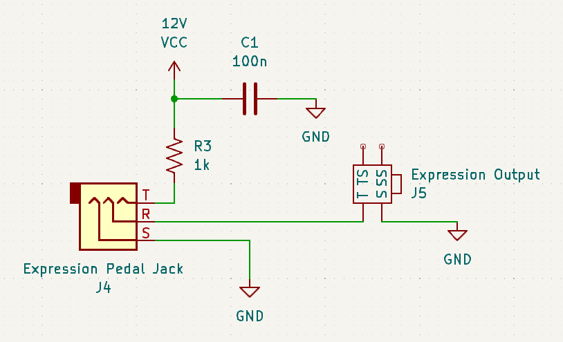
Now on to the expression pedal. A 1/4″ TRS cable is used for it as well. All the expression pedal really is, is just a potentiometer. The wiring may vary, but the standard pedal connects the tip to one side of the pot with the sleeve on the other side. The wiper of the pot is connected to the ring of the TRS cable. I think in the alternate wiring, the tip and ring may be reversed. That’s what the switch on the Moog EP-3 changes between. In addition, many expression pedals have an attenuator knob on the side. This just changes the maximum voltage at the output. You could also run the output through another module to attenuate, offset, or invert it.

Back to our eurorack receiving module, we have a 1/4″ TRS jack with the tip connected to 12V through a 1k resistor and the sleeve connected to ground. The ring connects directly to our output. This way, when we sweep the expression pedal, we are generating a voltage from 0V to approximately 10V.

Conclusion

That’s really all there is to it. You could tailor these circuits to your exact needs by adding attenuators or voltage dividers to obtain voltages in other ranges. It’s a pretty simple circuit to assemble, but if you don’t have the spare parts, time, and curiosity, you are likely better off to just buy the Doepfer A-177-2 and be done with it.

Until next time…

DJTW Dual LPG

Versatility or Confusing?

The DJ Thomas White Dual LPG is a nice sounding resonant filter to be sure. I think that the quality of the vactrols makes a pretty big impact on the sound. This can be a problem since vactrols are harder and harder to find.

This module is very well laid out for a variety of uses. The ability to easily customize the inputs and outputs, as well as the power connection is pretty cool. This is also one of its biggest problems. If you just jump straight in without doing a lot of research first, you are bound to make mistakes.

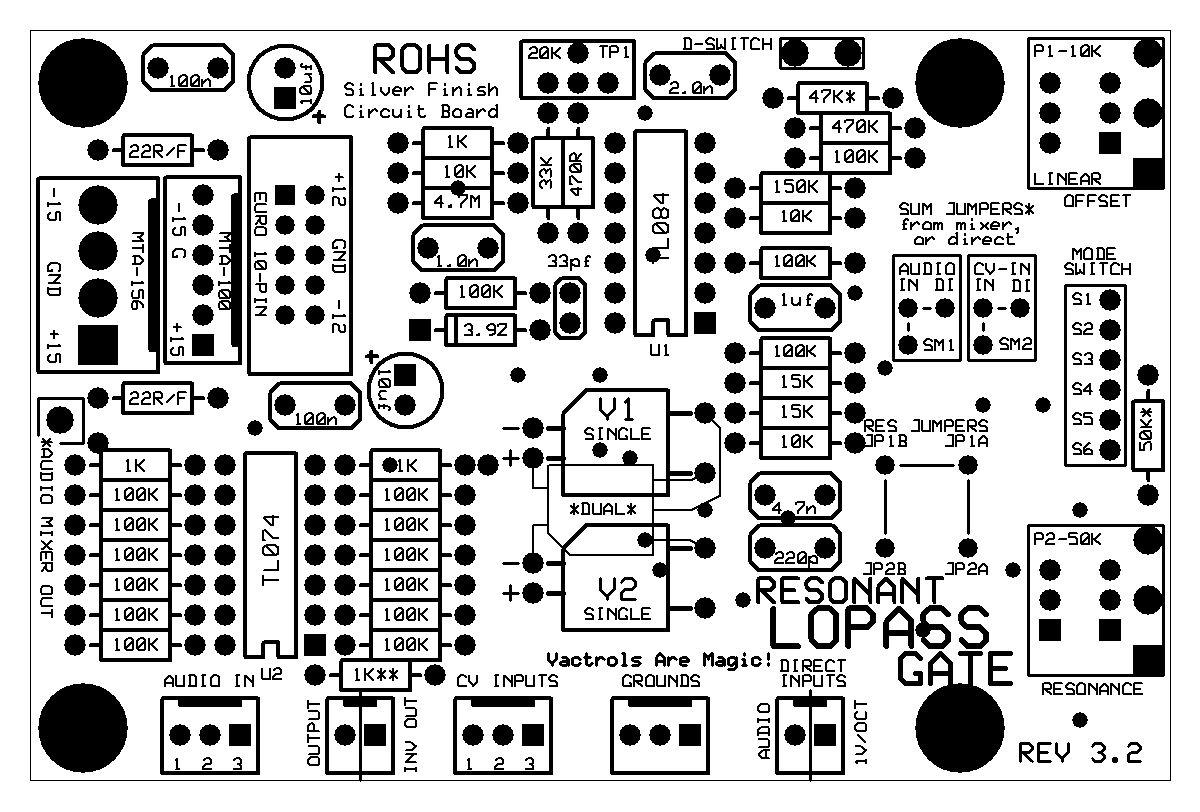
The version I was working on was the Dual LPG, so I had two of the boards at the top of this post. Each of these boards contains circuits for the filter / LPG channel, as well as an audio mixer circuit and a CV mixer circuit. If you are building a dual or quad version, you would need to wire things differently. Every component is not even used on every board. You configure it for your own purposes. The lack of documentation is frustrating to say the least.

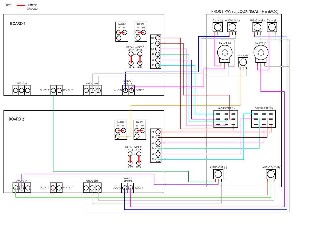
The most useful thing I found during all of my searching was a zip file containing docs gathered from modwiggler. I am including a few diagrams that are contained in that collection.

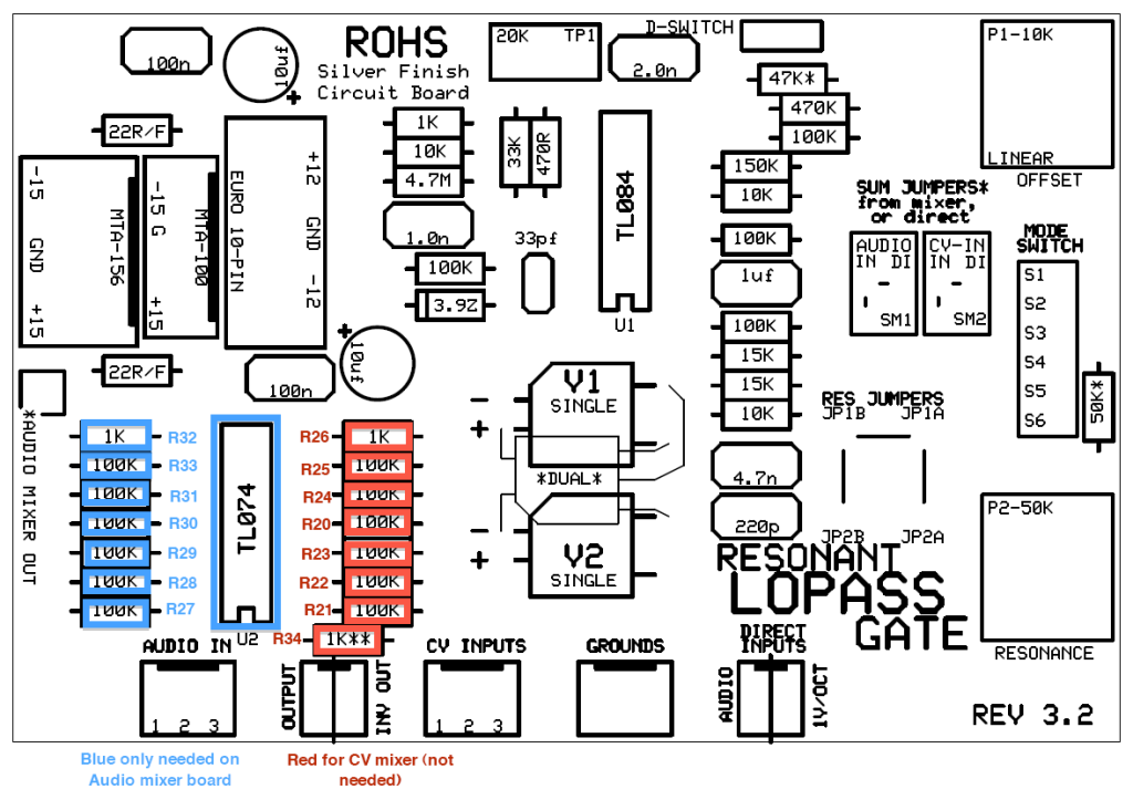
As you can see, this first image is a pretty clear illustration of how to wire two of these boards together. Some of the most notable things to pay attention to are the “Audio” and “CV-In” jumpers, as well as the “Res” jumpers. In addition to those, which are the same on both boards, the “Audio Mixer” is being used on “Board 2” and if you look carefully, the “Mix Out” jack is wired to a pad that is underneath the “Audio” jumper. The way this works is that the header at the bottom left corner of the board is connected to the TL074 mixer circuit and the output of that circuit is the pad near the “Audio” jumper. There is also a header (not shown in diagram) that allows multiple CV jacks to be input and a similar CV mixer that utilizes the other half of the TL074. For this Synthcube style Dual LPG panel and PCB kit, there is only one CV input and one Audio input, but you could potentially have 3 inputs for each and mix them on each channel. It opens up some interesting possibilities for the more extreme DIY enthusiast. On the example above, “Board 1” is not using the mixer section of that PCB at all, so you can actually leave several components off of that board. See below.

Feel free to comment below any questions you might have. This has only been a basic overview of the challenges I encountered while attempting this build. At some point in the future, I may attempt a redesign of this, making it a eurorack exclusive build and fix the other glaring problem it has, which is that it is about 5 inches deep when assembled.

Until next time…

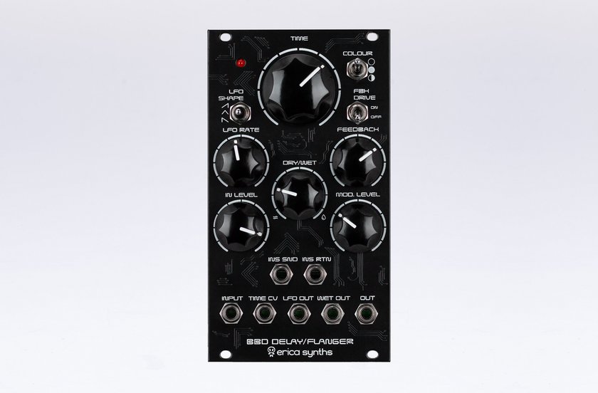
Feedback Drive of Erica Synths DIY BBD/Flanger Analysis

Today, I would like to go over the feedback drive circuit of the Erica Synths BBD/Flanger. Let’s jump right into it.

The Switch

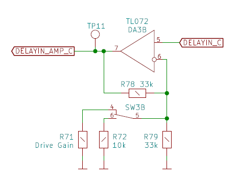
SW3 is a double pole, double throw switch. In the center position, there is no “drive” and at up or down, it switches between 2 pairs of diodes (or LEDs) and 2 resistors or different values simultaneously. The resistors balance the gain between the two drive flavors and you will need to choose these resistors carefully for your specific module. As you can see below, there are 6 diodes shown on the schematic, however, only 4 are to be populated.

LEDs or Diodes?

You may use either LEDs or diodes in two of the VD6, VD7, VD10, and VD11 spots. VD4 and VD5 are meant to be 1N4148 silicon diodes. If you choose to use LEDs in the other drive spot, you would populate them in VD7 and VD10. You could use a different pair of diodes, such as BAT41 schottky diodes in the VD6 and VD11 spaces instead. The feedback drive switch, it simultaneously switches the diode pair and the resistor in the gain circuit (R71 or R72). This is where confusion begins to creep in for the builder. The BOM shows R71 as NU (not used) and R72 is shown as 10k. The schematic shows R71 as “Drive Gain” and R72 as 10k once again.

Mixed Signals in the Documents Leads to Confusion

The third source of information, the “Guide To Assembly” contains the following text at step 4 of the instructions.

“Next to the FEEDBACK DRIVE switch you’ll find solder pads for overdrive diodes. You can use any diodes of your taste for pairs VD4/VD5 and VD6/VD11 or VD7/VD10 which are LEDs. The kit contains two red LEDs (if you use LEDs, do not populate VD6/VD11) and 1N4148 for VD4/VD5. You may experiment here with different diodes (try germanium diodes for softer overdrive) of LEDs of various colours it will result in different overdrive flavour. I used 33k for R71 and 100k for R72 in the overdrive configuration supplied with a kit.”1

As you can see, in the build guide, Erica Synths calls out that they used 33k for R71 and 100k for R72. If you make this mistake, you will have a module that has a severe volume change when switching between those drive flavors. I’ll be honest, it has been a month or so since I worked on this module and I don’t remember the exact resistor values I used, but that is also not important. The important part is that you figure out the correct value for the module you are building. In step 7 of Erica’s build document they state this: R71 sets the gain for VD4/VD5 and R72 sets the gain for LEDs (VD6/VD11 or VD7/VD10). You need to adjust the gain of the feedback signal so that the module goes into self-oscillation at approximately the same settings for all switch positions.

Resource for Diode / LED Clipping

As I studied this part of the build, I found a webpage that does a fantastic job of describing saturation flavors from a variety of diodes and LEDs.

https://www.guitarpedalx.com/news/gpx-blog/a-brief-hobbyist-primer-on-clipping-diodes

Several circuits listed there, as well as comparisons between the diodes and LEDs. It is a great resource if you are building this module or anything else where diode clipping is involved. At some point in the future, I have a plan to build a diode clipper circuit from scratch. Distortion and saturation is one of my favorite things, so stay tuned for that.

Footnotes
  1. https://www.ericasynths.lv/media/BBD_Delay_manual_assembly1.pdf ↩︎

Figuring all of this out…

I had forgotten what a chore it is to set up a WordPress site. I’m sure that professionals have much better ways of doing all this. I am slowly working my way through this and getting a little more comfortable with the process. There are a lot of things left to do though.

I moved my original post over to an About page and added a little more context to it since that post was mostly an introduction to what I am trying to accomplish here.

What brought me to this point and gave me the idea to attempt this was a bulk purchase I made from someone I met on Facebook. There were several DIY modules that had been started or half built. These included a couple that I have finished already – Erica Synths DIY BBD / Flanger and a Thomas White Dual LPG. The Erica Synths module was more or less complete, but had some small issues that I corrected. The Dual LPG, on the other hand, was only half built. I finished it and still had issues with the half that I completed. Eventually, I tried replacing two vactrols and this got it to a point where I am happy with it. The only problem is that the two halves respond and sound slightly different because of the vactrol differences. The vactrols all have the same part numbers, but they are different brands and from different times.

I also had a look at a module that I had never heard of called Miasma, made by someone called Sin Phi. As I searched for clues about this module, I discovered that it is a slight redesign of the Befaco Rampage. More research uncovered that the PCB that I had found is an early prototype and not even worth building because of how many errors it contains. At this point, I still wanted to build it because I was invested, so I found a github page where someone has updated it somewhat. There were PCB fabrication files there along with a BOM, but no instructions. The BOM is also not very good. I sent the files off to a PCB place and had 5 of these Miasmas produced. I’ve built three of those so far and made some mistakes on the first two. I’ll have to revisit those at some point soon. The third one seems to work pretty well. There are some oddities about the way it works though and I have never used a Rampage, so I am unsure if it has the same behaviors.

Some other modules from this lot that I need to complete are the Stroh / J3rk 258 Dual Oscillator and the 291 Dual Filter. These are particularly intriguing because of sets of pads meant for modifications. The lack of documentation is concerning though. I also found some Plan B Dual LPG PCBs that I don’t have a lot of information about. I believe I found the boards on the CGS website. I could totally see redesigning these old J3rk and Plan B modules with updated designs, eliminating the need for wiring panels to the PCB and condensing the components down to a more manageable design. I am unsure if the Plan B boards are even supposed to be for eurorack at all.

Until next time…