Versatility or Confusing?
The DJ Thomas White Dual LPG is a nice sounding resonant filter to be sure. I think that the quality of the vactrols makes a pretty big impact on the sound. This can be a problem since vactrols are harder and harder to find.
This module is very well laid out for a variety of uses. The ability to easily customize the inputs and outputs, as well as the power connection is pretty cool. This is also one of its biggest problems. If you just jump straight in without doing a lot of research first, you are bound to make mistakes.
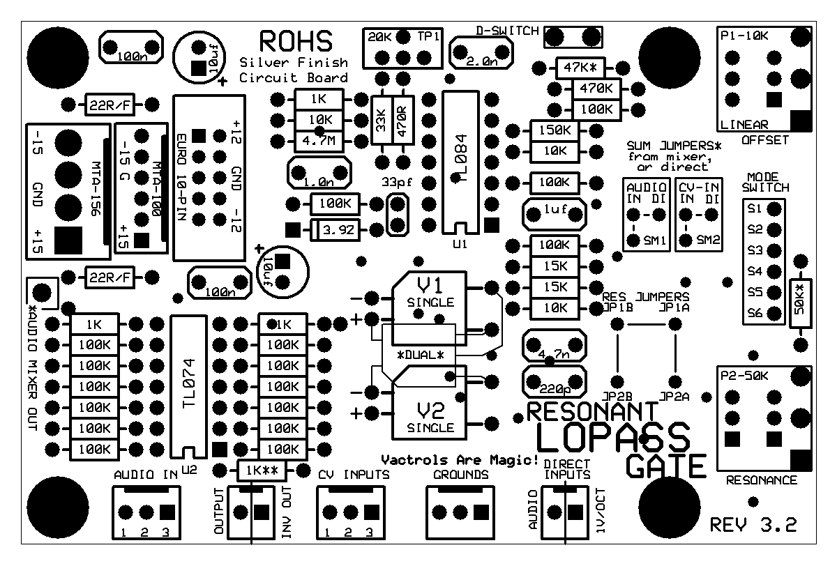
The version I was working on was the Dual LPG, so I had two of the boards at the top of this post. Each of these boards contains circuits for the filter / LPG channel, as well as an audio mixer circuit and a CV mixer circuit. If you are building a dual or quad version, you would need to wire things differently. Every component is not even used on every board. You configure it for your own purposes. The lack of documentation is frustrating to say the least.
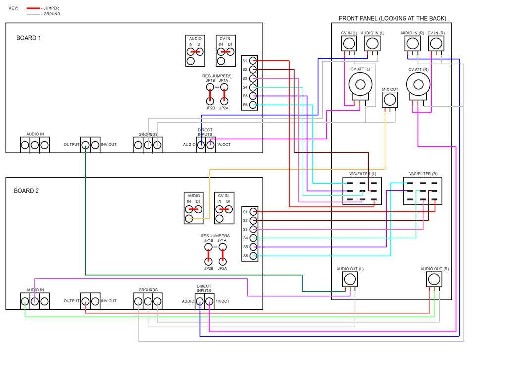
The most useful thing I found during all of my searching was a zip file containing docs gathered from modwiggler. I am including a few diagrams that are contained in that collection.

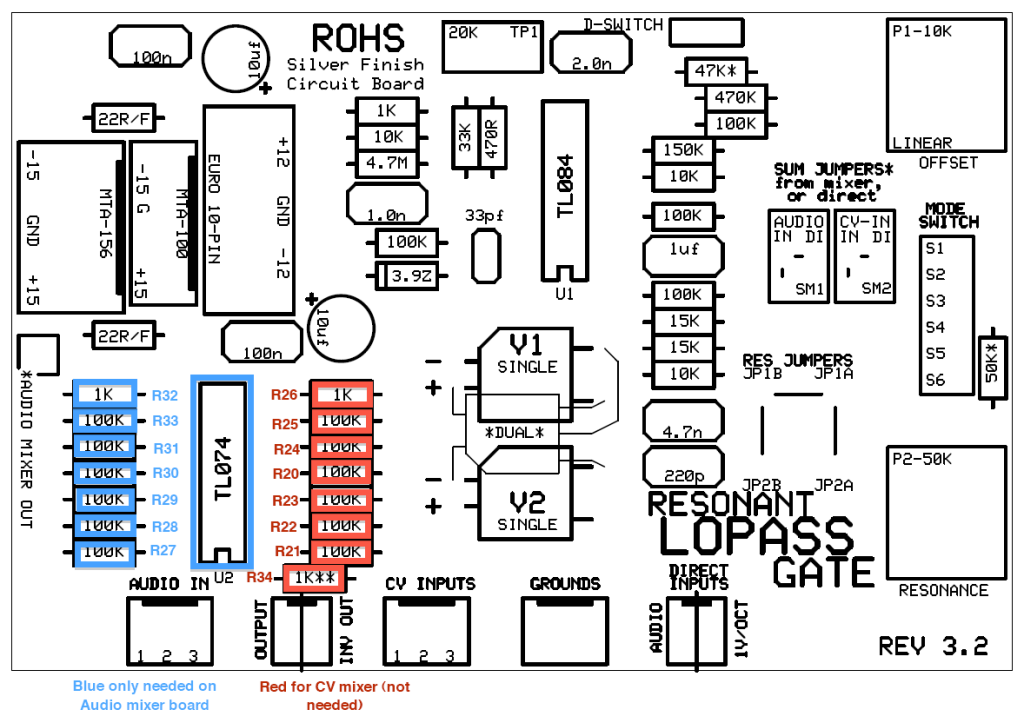
As you can see, this first image is a pretty clear illustration of how to wire two of these boards together. Some of the most notable things to pay attention to are the “Audio” and “CV-In” jumpers, as well as the “Res” jumpers. In addition to those, which are the same on both boards, the “Audio Mixer” is being used on “Board 2” and if you look carefully, the “Mix Out” jack is wired to a pad that is underneath the “Audio” jumper. The way this works is that the header at the bottom left corner of the board is connected to the TL074 mixer circuit and the output of that circuit is the pad near the “Audio” jumper. There is also a header (not shown in diagram) that allows multiple CV jacks to be input and a similar CV mixer that utilizes the other half of the TL074. For this Synthcube style Dual LPG panel and PCB kit, there is only one CV input and one Audio input, but you could potentially have 3 inputs for each and mix them on each channel. It opens up some interesting possibilities for the more extreme DIY enthusiast. On the example above, “Board 1” is not using the mixer section of that PCB at all, so you can actually leave several components off of that board. See below.

Feel free to comment below any questions you might have. This has only been a basic overview of the challenges I encountered while attempting this build. At some point in the future, I may attempt a redesign of this, making it a eurorack exclusive build and fix the other glaring problem it has, which is that it is about 5 inches deep when assembled.
Until next time…
