Recently, I bought the Qu-Bit Stardust, which is a “cosmic” tape looper. It’s actually a really cool looper and I have not used loopers very much. My reason for adding this to my collection is to have a way to layer recordings from non eurorack synthesizers (traditional synths). Immediately, I found a need for a way to punch in and out of recording easily so that I could play along with the loop, but then punch in to record a new part without breaking my “flow”. A footswitch seemed to be the obvious answer, but the implementation in my eurorack system was not so obvious. I had never really considered how a footswitch (or expression pedal) works, so my first course of action was to figure that out.
The Setup
For this example, I am using a Boss FS-6 Dual Footswitch and a Moog EP-3 Expression Pedal. The Boss FS-6 contains a 9V battery and there are switches on the back to allow each of the footswitches to reverse polarity and work in either “Latch” mode or “Momentary” mode. The Moog EP-3 also has a switch on the bottom to switch between “Standard” or “Other”. In addition the EP-3 also has a trimmer knob on the side that “scales the output” according to the Moog writeup about it. I will get into what these do shortly.
What are we even talking about?
First off, a footswitch is just a switch. By engaging / stepping on the switch, you are just closing (or opening) a circuit. This is the first important concept to grasp. The second thing to note is that the footswitch may be opening or closing the circuit. The FS-6 has a polarity switch that allows you to set it either way. The last thing is that the FS-6 can be latched or momentary. For this example, we are going to have the polarity set to normally closed and the latching on. This way, when the footswitch is “off”, the circuit is actually completed through the footswitch. When the footswitch is “on”, the circuit is broken within the footswitch and it remains broken until the footswitch is clicked again.
So, let’s say for an example that we want to send a gate signal to that Stardust looper that I mentioned earlier. We would have to route a constant voltage through our footswitch and when we step on the footswitch, it passes that voltage to the looper. If this voltage remains high, the looper records. Stepping on the footswitch again would open the circuit and the looper stops recording. Let’s get into how this actually works.
The Dual Footswitch Circuit
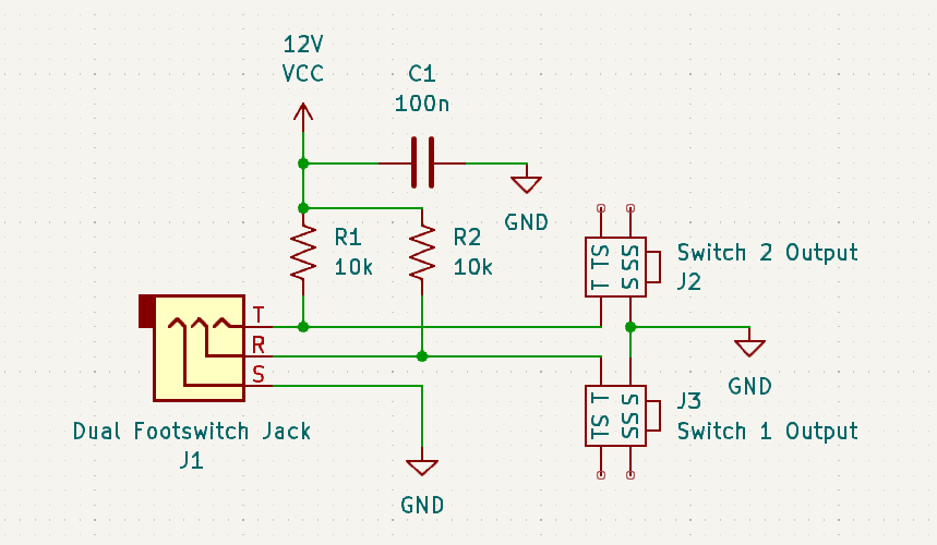
A dual footswitch connects to a device with a typical 1/4″ TRS cable. The tip and ring are connected to switch 1 and switch 2 of the dual footswitch and the sleeve is a common return for both. So on the receiving module in the eurorack system, we have a 1/4″ TRS jack. The positive 12V connects to the tip and the ring of this jack through 2 10k resistors. When I started to research this simple circuit, I immediately found that Doepfer solved this for us a long time ago with the A-177-2 module. It’s such a simple module, that I was able to reverse engineer it from photos alone.

Imagine the dual footswitch plugged into that circuit with the first switch connected to the ring and sleeve of the TRS cable. When the switch is “off” (closed), 12V flows through a 10k resistor and gets shorted to ground through the switch. You press the switch and it latches “on”, which opens the switch and now that 12V does not short to ground any longer, instead it becomes present on the Switch 1 Output jack, giving us approximately a 10V gate output. The same thing happens for Switch 2.
Express Yourself
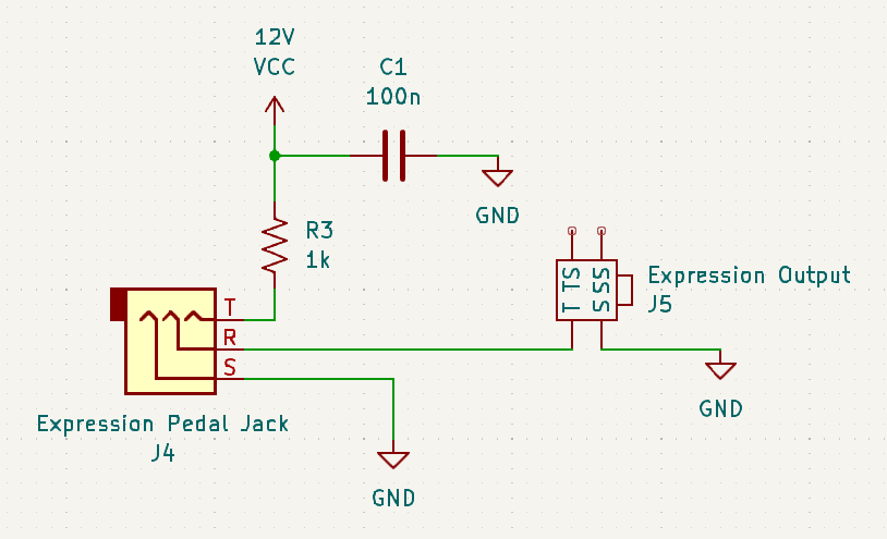
Now on to the expression pedal. A 1/4″ TRS cable is used for it as well. All the expression pedal really is, is just a potentiometer. The wiring may vary, but the standard pedal connects the tip to one side of the pot with the sleeve on the other side. The wiper of the pot is connected to the ring of the TRS cable. I think in the alternate wiring, the tip and ring may be reversed. That’s what the switch on the Moog EP-3 changes between. In addition, many expression pedals have an attenuator knob on the side. This just changes the maximum voltage at the output. You could also run the output through another module to attenuate, offset, or invert it.
Back to our eurorack receiving module, we have a 1/4″ TRS jack with the tip connected to 12V through a 1k resistor and the sleeve connected to ground. The ring connects directly to our output. This way, when we sweep the expression pedal, we are generating a voltage from 0V to approximately 10V.

Conclusion
That’s really all there is to it. You could tailor these circuits to your exact needs by adding attenuators or voltage dividers to obtain voltages in other ranges. It’s a pretty simple circuit to assemble, but if you don’t have the spare parts, time, and curiosity, you are likely better off to just buy the Doepfer A-177-2 and be done with it.
Until next time…
